The seed for this project starts back in the December of 2019 when I was working on a drone project for 96Boards. Along with the usual suspects in a drone kit, I had bought the Flysky FS-i6s controller. Midway through, it struck me how odd it is that after all the improvements in microcontrollers and communications, drones still relied on analog PWM to communicate from the remote controller to the flight controller onboard the drone. Although the BECs undoubtedly would need a PWM signal to control the RPM, we have some smart ones now that don't and are indeed digital, using PWM to send commands to the flight computer seemed odd and an unnecessary bloat from a gone by era. It's not even PCM!
I had gone quite a bit further in my quest, blog part 2 laid out the plan and blog part 3 had some further success.
However, I hadn't made the controller side of the story digital, my flysky-i6s was still spewing out analog PWM and something needed to be done, but of course by then the world had to take a few years off, and I got myself involved in other long term projects. Which brings us here.
The Hardware
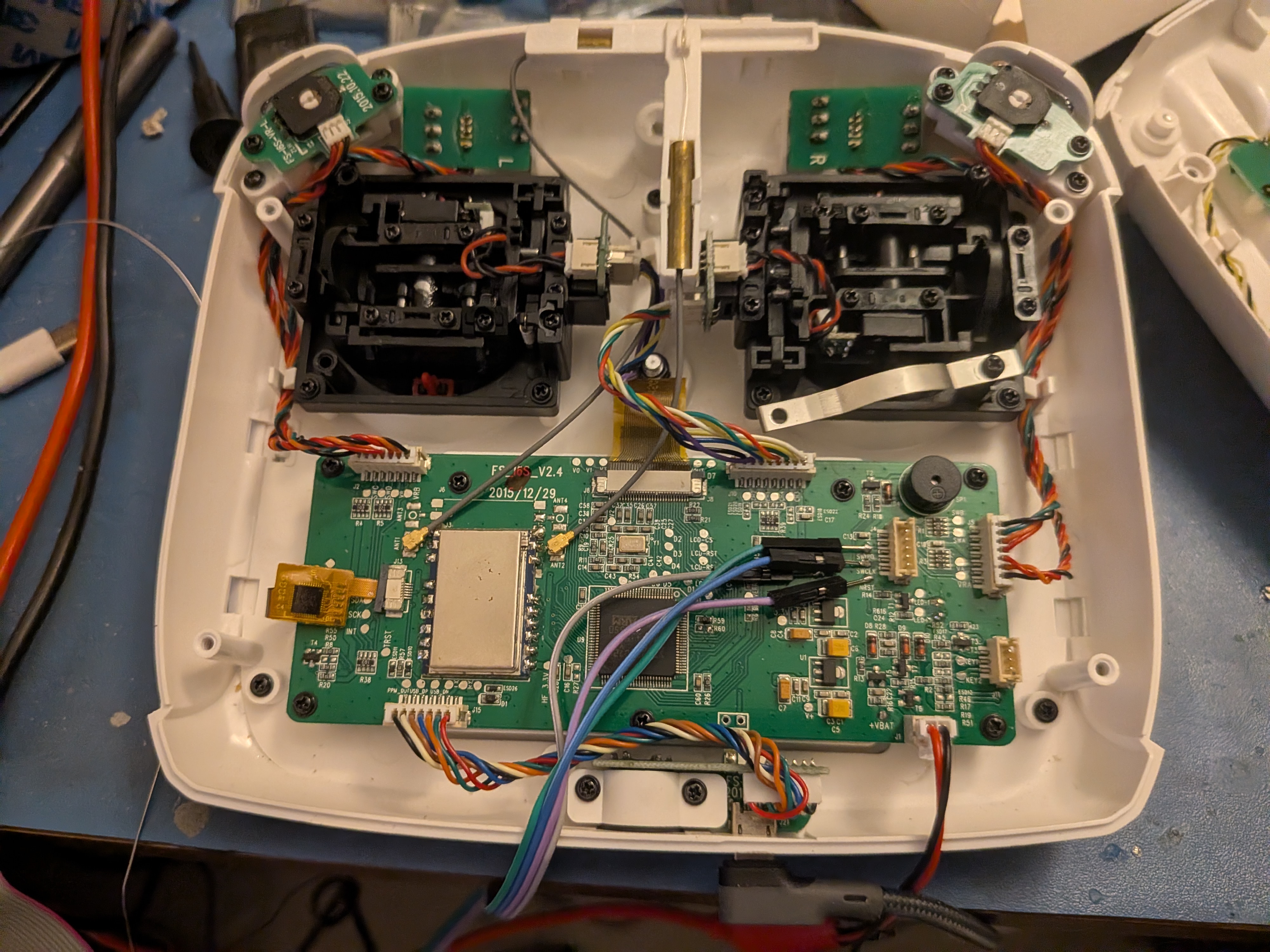
The i6s is a pretty neat kit, tons of control surfaces, a decent monochrome touchscreen LCD and a STM32F072VB at its heart.
The PCB itself is well laid out and every thing connected to the MCU has an exposed test point, My initial thought was to reverse engineer the pinout by monitoring all the pins and then externally driving the testpoints high/low and monitoring the change. But luckily someone had already done the hard work. Looks like Simon Schulz had a similar idea and did the reverse engineering work already for his own firmware.
The Lay of the Land
SWD Debug
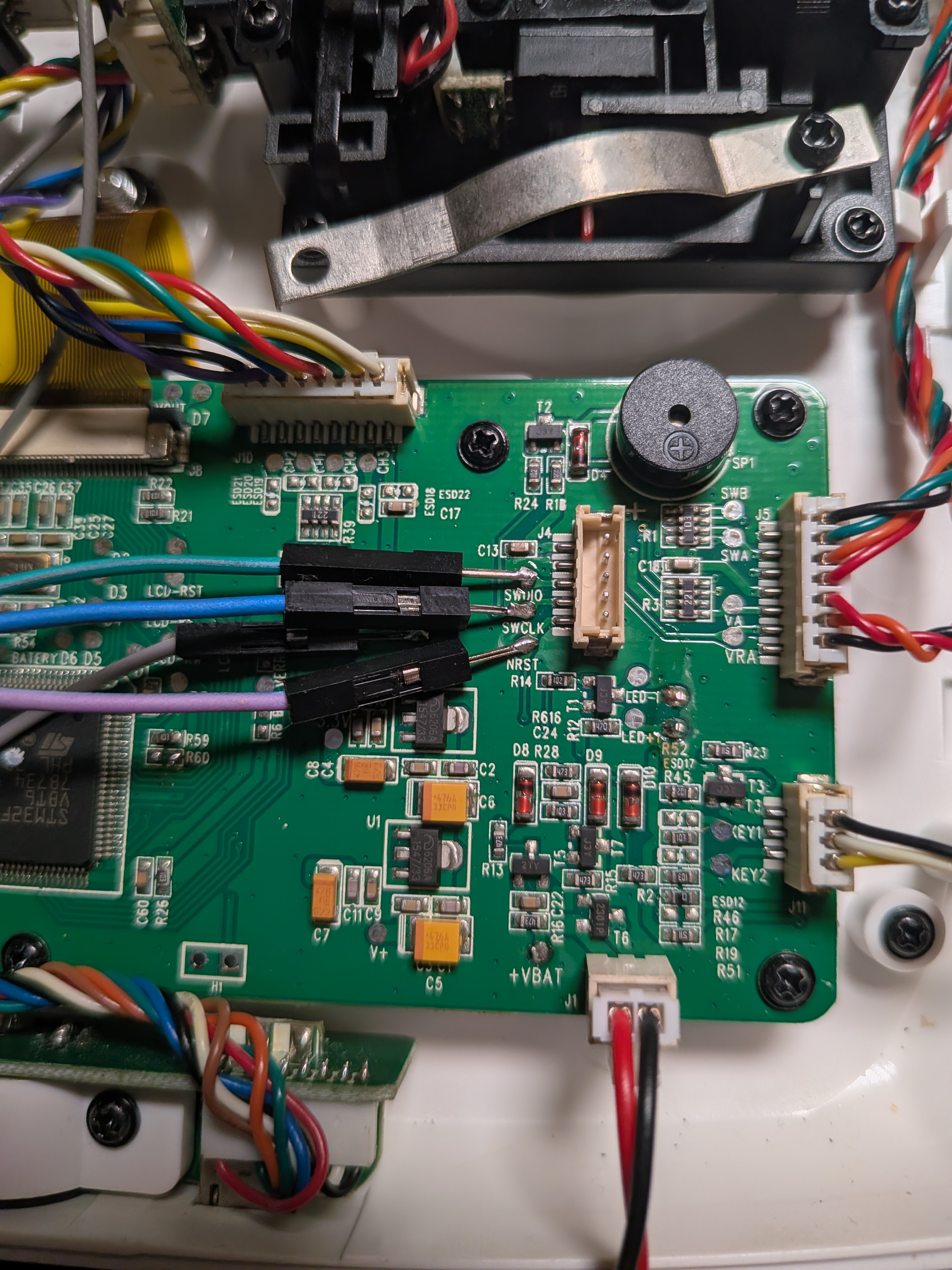
The only unconnected header labeled J4 breaks out the SWD pins, you could either get and appropriate connector, which I assume would be 2.0mm JST header or solder directly to the aptly labeled testpoints as I did. You'd only need this connector header once, to remove any write protection that might be in place and to clear out the EEPROM using STM32Cube tools. Once that is done you can just use DFU over USB to flash. To get the hardware into DFU mode requires another mod.
DFU over USB
To enable flashing via DFU, you'll need to go connect via SWD to STM32CubeProgrammer and unlock all the flash blocks, once that is done you can short cross resistor R60 while powering on or add two buttons, one for boot mode across R60 and other for reset from the NRST pad to GND and reset the controller while holding the boot button, this will make the controller show up as a generic STM32 DFU device that can be flashed via openOCD.
The Zephyr port has both SWD and DFU methods enabled so west flash works by default.
GIPO Buttons
Only the power button pair and back buttons use raw gpio input. Both the power buttons are connected to a single gpio and need to be pressed together to trigger the action, usually designed this way as a safety lock. On the original firmware they were used for triggering low power mode by turning off the radio and display etc.
The pair of buttons on the back of the controller get their individual GPIOs.
Pinout:
    POWERBUTTON_BOTH  = PB14
    BUTTON_BACK_RIGHT = PA10
    BUTTON_BACK_LEFT  = PA9
Devicetree:
    buttons {
        compatible = "gpio-keys";

        power_button_pair: power_button {
            label = "Power Button Pair";
            gpios = <&gpiob 14 GPIO_ACTIVE_LOW>;
            zephyr,code = <INPUT_KEY_POWER>;
        };

        back_button_right: right_button {
            label = "Back Right Button";
            gpios = <&gpioa 10 GPIO_ACTIVE_LOW>;
            zephyr,code = <INPUT_BTN_RIGHT>;
        };

        back_button_left: left_button {
            label = "Back Left Button";
            gpios = <&gpioa 9 GPIO_ACTIVE_LOW>;
            zephyr,code = <INPUT_BTN_LEFT>;
        };
    };
LEDs
There are 3 total LEDs, one for each power button. Even though the power buttons themselves are connected to the same GPIOs, they each get their individual LEDs. A third LED is for the LCD backlight. Unfortunately the backlight LED is not connected to a PWM capable GPIO so unless one wants to spend precious cycles running softPWM, the only control available is on and off.
Pinout:
    LED_BACKLIGHT = PF3 = PIN 22
    BUTTON_LEFT_BLUE = PD10
    BUTTON_RIGHT_BLUE = PD11
Devicetree:
    leds {
        compatible = "gpio-leds";

        led_backlight: led_backlight {
            gpios = <&gpiof 3 GPIO_ACTIVE_HIGH>;
            label = "LED Backlight";
        };

        blue_left_button: led_left {
            gpios = <&gpiod 10 GPIO_ACTIVE_HIGH>;
            label = "Button Left LED";
        };

        blue_right_button: led_right {
            gpios = <&gpiod 11 GPIO_ACTIVE_HIGH>;
            label = "Button Right LED";
        };
    };
Buzzer
There is a buzzer onboard which was used for audible feedback during touch inputs, to drive it just the PWM width. For the Zephyr upstream board support I have set the frequency to 1500 uSeconds, at par with some other boards that include a buzzer.
Pinout:
BUZZER = PA8 = PIN67 (TIM1_CH1)
Devicetree:
    zephyr,user {
        pwms = <&pwm1 1 PWM_USEC(1500) PWM_POLARITY_NORMAL>;
    };
    &timers1 {
        st,prescaler = <10000>;
        status = "okay";

        pwm1: pwm {
            status = "okay";
            pinctrl-0 = <&tim1_ch1_pa8>;
            pinctrl-names = "default";
        };
    };
ADC
This is by far the meatiest part of this controller's story, almost every control, except for the back buttons, are mapped to the 11 channels on ADC 1. Even the two pairs of switches on each side are laddered resistor array instead of a binary on off.
Luckily for me, Zephyr has developed a healthy set of analog drivers, primary for controllers like this, which makes the fact that the fs-i6s is the first upstream controller even more surprising.
However, this approach reveals an interesting problem, the STM32F072VB is not a powerful MCU, its one of the slowest Cortex-M MCUs I have ever seen. It's a Cortex-M0 non-plus running at 48MHz, 3 stage in-order. And this matters because it's too slow to poll all the ADC channels effectively and very often runs into ADC overrun issues and crashes out.
The two ways to fix the problem is to detach the ADC's sampling clock from bus clock so that it runs slower, ie in ASYNC mode. The second is to enable DMA. Both of these solutions took me for a spin.
The ADC block in this MCU always has its own 14MHz clock enabled for sampling and only prescaler values of 1, 2 and 4 are valid. When you take a look at the devicetree it seems that the clock is synced to HSI but on this MCU there is no ASYNC option to route a slower clock like LSI or HSE with a larger divide value, the ADC sampler is always driven by its own 14MHz clock. So as far as this situation is concerned, there is no wiggle room. Even the highest acquisition time setting will cause ADC overruns without DMA.
As for setting up the DMA, there was some confusion with DMA channel and config. In most other STM32 each block's DMA has Rx and Tx channels, we then add a 0 in the devicetree node to ignore one of the channels if that channel is not required. In case of this MCU the DMA for the ADC block is not very configurable and doesn't have a Tx channel at all. Solving that and figuring out the correct DMA flags enabled DMA for the ADC and removed all overrun errors.
After playing a bit with the analog value thresholds and dead zones, the inputs seemed pretty solid.
ADC Pinout:
    STICK_LR_RIGHT = PA0 (ADC_CH0)
    STICK_UD_RIGHT = PA1 (ADC_CH1)
    STICK_UD_LEFT  = PA2 (ADC_CH2)
    STICK_LR_LEFT  = PA3 (ADC_CH3)
    2WAY_SWA_LEFT  = PA4 (ADC_CH4)
    3WAY_SWB_LEFT  = PA5 (ADC_CH5)
    JOG_VAA_LEFT   = PA6 (ADC_CH6)
    JOG_VAB_RIGHT  = PA7 (ADC_CH7)
    3WAY_SWC_RIGHT = PB0 (ADC_CH8)
    2WAY_SWD_RIGHT = PB1 (ADC_CH9)
    BATTERY_V      = PC0 (ADC_CH10)
ADC Devicetree:
    &adc1 {
        pinctrl-0 = <&adc_in0_pa0 &adc_in1_pa1
            &adc_in2_pa2 &adc_in3_pa3
            &adc_in4_pa4 &adc_in5_pa5
            &adc_in6_pa6 &adc_in7_pa7
            &adc_in8_pb0 &adc_in9_pb1
            &adc_in10_pc0>;
        pinctrl-names = "default";
        #address-cells = <1>;
        #size-cells = <0>;
        status = "okay";

        st,adc-clock-source = "SYNC";
        st,adc-prescaler = <4>;

        dmas = <&dma1 1
            (STM32_DMA_PERIPH_TO_MEMORY | STM32_DMA_MEM_INC | STM32_DMA_PRIORITY_HIGH |
            STM32_DMA_MEM_16BITS | STM32_DMA_PERIPH_16BITS)>;
        dma-names = "dmamux";

        vref-mv = <3300>;

        channel@0 {
            reg = <0>;
            zephyr,gain = "ADC_GAIN_1";
            zephyr,reference = "ADC_REF_INTERNAL";
            zephyr,acquisition-time = <ADC_ACQ_TIME(ADC_ACQ_TIME_TICKS, 42)>;
            zephyr,resolution = <12>;
        };

        channel@1 {
            reg = <1>;
            zephyr,gain = "ADC_GAIN_1";
            zephyr,reference = "ADC_REF_INTERNAL";
            zephyr,acquisition-time = <ADC_ACQ_TIME(ADC_ACQ_TIME_TICKS, 42)>;
            zephyr,resolution = <12>;
        };

        channel@2 {
            reg = <2>;
            zephyr,gain = "ADC_GAIN_1";
            zephyr,reference = "ADC_REF_INTERNAL";
            zephyr,acquisition-time = <ADC_ACQ_TIME(ADC_ACQ_TIME_TICKS, 42)>;
            zephyr,resolution = <12>;
        };

        channel@3 {
            reg = <3>;
            zephyr,gain = "ADC_GAIN_1";
            zephyr,reference = "ADC_REF_INTERNAL";
            zephyr,acquisition-time = <ADC_ACQ_TIME(ADC_ACQ_TIME_TICKS, 42)>;
            zephyr,resolution = <12>;
        };

        channel@4 {
            reg = <4>;
            zephyr,gain = "ADC_GAIN_1";
            zephyr,reference = "ADC_REF_INTERNAL";
            zephyr,acquisition-time = <ADC_ACQ_TIME(ADC_ACQ_TIME_TICKS, 42)>;
            zephyr,resolution = <12>;
        };

        channel@5 {
            reg = <5>;
            zephyr,gain = "ADC_GAIN_1";
            zephyr,reference = "ADC_REF_INTERNAL";
            zephyr,acquisition-time = <ADC_ACQ_TIME(ADC_ACQ_TIME_TICKS, 42)>;
            zephyr,resolution = <12>;
        };

        channel@6 {
            reg = <6>;
            zephyr,gain = "ADC_GAIN_1";
            zephyr,reference = "ADC_REF_INTERNAL";
            zephyr,acquisition-time = <ADC_ACQ_TIME(ADC_ACQ_TIME_TICKS, 42)>;
            zephyr,resolution = <12>;
        };

        channel@7 {
            reg = <7>;
            zephyr,gain = "ADC_GAIN_1";
            zephyr,reference = "ADC_REF_INTERNAL";
            zephyr,acquisition-time = <ADC_ACQ_TIME(ADC_ACQ_TIME_TICKS, 42)>;
            zephyr,resolution = <12>;
        };

        channel@8 {
            reg = <8>;
            zephyr,gain = "ADC_GAIN_1";
            zephyr,reference = "ADC_REF_INTERNAL";
            zephyr,acquisition-time = <ADC_ACQ_TIME(ADC_ACQ_TIME_TICKS, 42)>;
            zephyr,resolution = <12>;
        };

        channel@9 {
            reg = <9>;
            zephyr,gain = "ADC_GAIN_1";
            zephyr,reference = "ADC_REF_INTERNAL";
            zephyr,acquisition-time = <ADC_ACQ_TIME(ADC_ACQ_TIME_TICKS, 42)>;
            zephyr,resolution = <12>;
        };

        channel@a {
            reg = <0x0a>;
            zephyr,gain = "ADC_GAIN_1";
            zephyr,reference = "ADC_REF_INTERNAL";
            zephyr,acquisition-time = <ADC_ACQ_TIME(ADC_ACQ_TIME_TICKS, 42)>;
            zephyr,resolution = <12>;
        };
    };

    &dma1 {
        status = "okay";
    };
Devicetree for the Analog Sticks and Rudder Wheel:
    analog_axis {
        compatible = "analog-axis";

        axis_r_x {
            io-channels = <&adc1 0>;
            in-deadzone = <100>;
            in-min = <300>;
            in-max = <3700>;
            zephyr,axis = <INPUT_ABS_RX>;
        };

        axis_r_y {
            io-channels = <&adc1 1>;
            in-deadzone = <100>;
            in-min = <300>;
            in-max = <3700>;
            zephyr,axis = <INPUT_ABS_RY>;
        };

        axis_l_y {
            io-channels = <&adc1 2>;
            in-deadzone = <100>;
            in-min = <300>;
            in-max = <3700>;
            zephyr,axis = <INPUT_ABS_Y>;
        };

        axis_l_x {
            io-channels = <&adc1 3>;
            in-deadzone = <100>;
            in-min = <300>;
            in-max = <3700>;
            zephyr,axis = <INPUT_ABS_X>;
        };

        vaa_x {
            io-channels = <&adc1 6>;
            in-deadzone = <100>;
            in-min = <400>;
            in-max = <3400>;
            zephyr,axis = <INPUT_ABS_WHEEL>;
        };

        vab_x {
            io-channels = <&adc1 7>;
            in-deadzone = <100>;
            in-min = <400>;
            in-max = <3400>;
            zephyr,axis = <INPUT_ABS_RUDDER>;
        };
    };
Devicetree for Resistor Ladder Switches:
    switch_a {
        compatible = "adc-keys";
        io-channels = <&adc1 4>;
        keyup-threshold-mv = <0>;

        key_0 {
            press-thresholds-mv = <3000>, <3300>;
            zephyr,code = <INPUT_KEY_0>;
        };
    };

    switch_b {
        compatible = "adc-keys";
        io-channels = <&adc1 5>;
        keyup-threshold-mv = <0>;

        key_0 {
            press-thresholds-mv = <1500>, <2300>;
            zephyr,code = <INPUT_KEY_X>;
        };

        key_1 {
            press-thresholds-mv = <2500>, <3300>;
            zephyr,code = <INPUT_KEY_B>;
        };
    };

    switch_c {
        compatible = "adc-keys";
        io-channels = <&adc1 8>;
        keyup-threshold-mv = <0>;

        key_0 {
            press-thresholds-mv = <1500>, <2300>;
            zephyr,code = <INPUT_KEY_Y>;
        };

        key_1 {
            press-thresholds-mv = <2500>, <3300>;
            zephyr,code = <INPUT_KEY_C>;
        };
    };

    switch_d {
        compatible = "adc-keys";
        io-channels = <&adc1 9>;
        keyup-threshold-mv = <0>;

        key_0 {
            press-thresholds-mv = <3000>, <3300>;
            zephyr,code = <INPUT_KEY_D>;
        };
    };
Devicetree for Batter Voltage Monitor:
    vbatt: voltage_divider {
        compatible = "voltage-divider";
        io-channels = <&adc1 10>;
        output-ohms = <5100>;
        full-ohms = <(10000 + 5100)>;
        status = "okay";
    };
Display
This controller has a pretty decent 2.42 inch monochrome LCD which looks great outdoors in direct sunlight. The panel itself is a HSG12864 and integrates a ST7567. Zephyr has support for the ST7567 controller, unfortunately it's tested only with the SPI interface and not the parallel 8080 interface, although it is enabled in the driver I wasn't able to get it to work. On top of that, this MCU does not have a native parallel LCD block so we need to use the bitbang driver to get the lcd working over GPIO. For now, I decided not to enable it upstream.
Pinout:
    LCD_D0  = PE0 = PIN 97
    LCD_D1  = PE1 = PIN 98
    LCD_D2  = PE2 = PIN  1
    LCD_D3  = PE3 = PIN  2
    LCD_D4  = PE4 = PIN  3
    LCD_D5  = PE5 = PIN  4
    LCD_D6  = PE6 = PIN  5
    LCD_D7  = PE7 = PIN 38
    LCD_RW  = PB5 = PIN 91
    LCD_RST = PB4 = PIN 90
    LDC_RS  = PB3 = PIN 89
    LCD_RD  = PD7 = PIN 88
    LCD_CS  = PD2 = PIN 83
Devicetree:
    zephyr_mipi_dbi_parallel: zephyr_mipi_dbi_parallel {
        compatible = "zephyr,mipi-dbi-bitbang";
        dc-gpios = <&gpiob 3 GPIO_ACTIVE_LOW>;
        reset-gpios = <&gpiob 4 GPIO_ACTIVE_LOW>;
        rd-gpios = <&gpiod 7 GPIO_ACTIVE_HIGH>;
        wr-gpios = <&gpiob 5 GPIO_ACTIVE_HIGH>;
        cs-gpios = <&gpiod 2 GPIO_ACTIVE_LOW>;
        data-gpios = <&gpioe 0 GPIO_ACTIVE_HIGH>,
            <&gpioe 1 GPIO_ACTIVE_HIGH>,
            <&gpioe 2 GPIO_ACTIVE_HIGH>,
            <&gpioe 3 GPIO_ACTIVE_HIGH>,
            <&gpioe 4 GPIO_ACTIVE_HIGH>,
            <&gpioe 5 GPIO_ACTIVE_HIGH>,
            <&gpioe 6 GPIO_ACTIVE_HIGH>,
            <&gpioe 7 GPIO_ACTIVE_HIGH>;
        #address-cells = <1>;
        #size-cells = <0>;
        status = "okay";

        st7567: st7567@0 {
            compatible = "sitronix,st7567";
            mipi-max-frequency = <1000000>;
            reg = <0>;
            width = <128>;
            height = <64>;
            column-offset = <0>;
            line-offset = <0>;
            regulation-ratio = <11>;
            bias;
            segment-invdir;
            mipi-mode = "MIPI_DBI_MODE_8080_BUS_8_BIT";
        };
    };
Touchscreen
The monochrome display has a pretty good capacitive touch screen on top, which is a combo that's rarely seen, so it feels a bit weird lol. The touch controller is a Focaltech FT6236 and is well supported in Zephyr.
Pinout:
    TOUCH_SCK = PB8  = PIN 95
    TOUCH_SDA = PB9  = PIN 96
    TOUCH_INT = PC12 = PIN 80
    TOUCH_RST = PA15 = PIN 77
Devicetree:
    &i2c1 {
        pinctrl-0 = <&i2c1_scl_pb8 &i2c1_sda_pb9>;
        pinctrl-names = "default";
        status = "okay";
        clock-frequency = <I2C_BITRATE_FAST>;

        ft6236: ft5336@38 {
            compatible = "focaltech,ft5336";
            reg = <0x38>;
            swapped-x-y;
            screen-width = <128>;
            screen-height = <64>;
            int-gpios = <&gpioc 12 GPIO_ACTIVE_LOW>;
            reset-gpios = <&gpioa 15 GPIO_ACTIVE_LOW>;
        };
    };
Radio
The only remaining component is the onboard radio, replacing that was the whole reason I started this project. For now, I am using an XBEE S2C pro module but in the future will probably replace that with a longer range Drone Telemetry module. I just had the XBEE lying around.
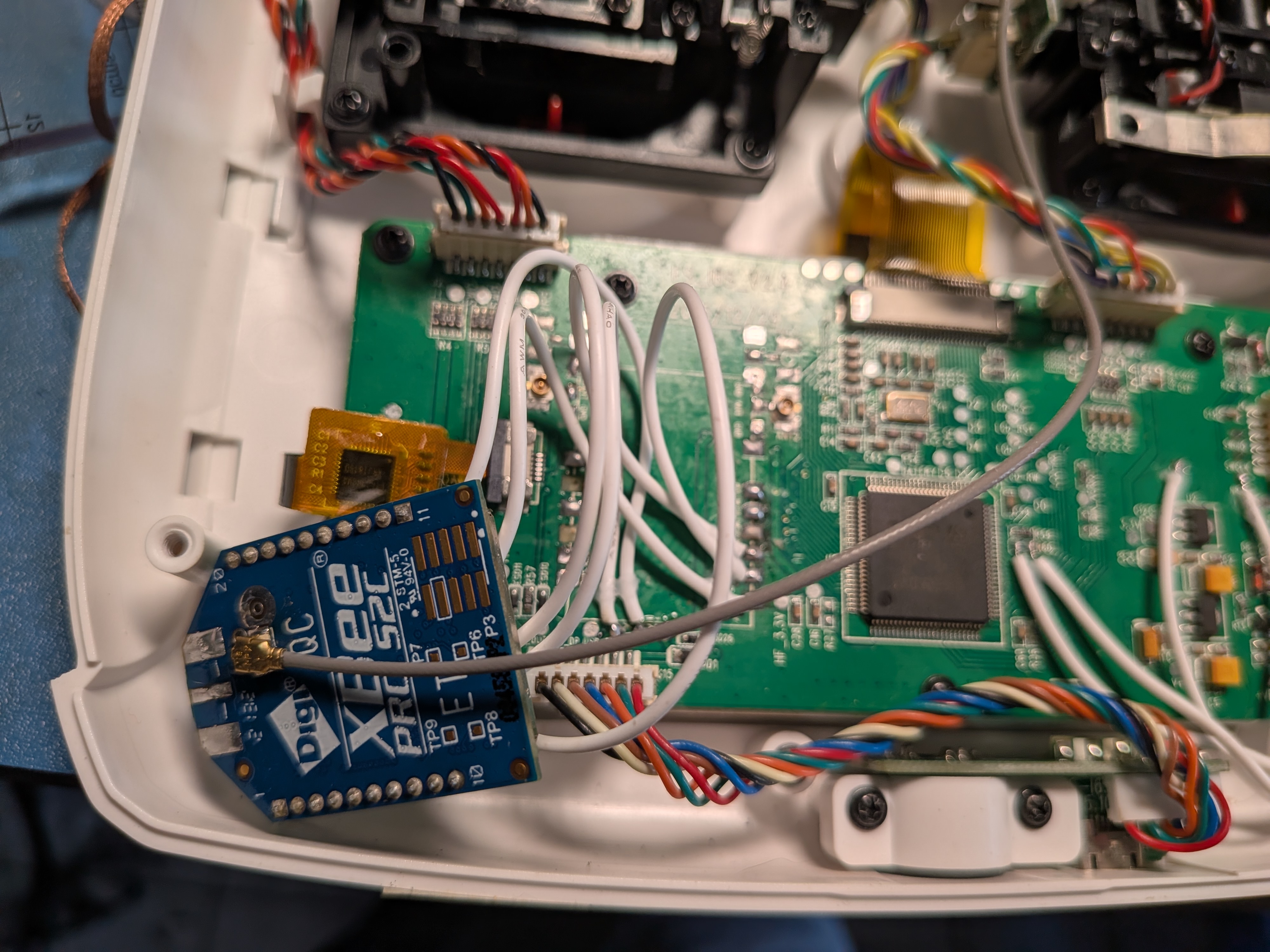
I was able to remove the original radio module with a lot of heat and persuasion, and replace it with the XBEE module on a separate board connected to the UART Port.
Pinout:
    RF_SDIO = PE15
    RF_SCK  = PE13
    RF_SCS  = PE12
    RF_RF1  = PE11
    RF_RF0  = PE10
    RF_RX-W = PE8
    RF_TX-W = PE9
    RF_GIO2 = PB2
    RF_GIO1 = PE14
Considerations
There are some aspects of the controller that aren't very suitable. Most of it has to do with the limited amount of memory, 16K might have been enough for the original firmware since it offloaded a fair bit of packetizing to the radio module over SPI, but this new setup uses the XBEE radio as a transparent UART, and it will manage data via MCTP or a similar protocol.
This also means that we are losing the only available UART to our radio module and do not have any other way to debug as CDC ACM over USB is extremely expensive, and we won't be able to run much more than a "Hello World!" example in the remaining memory.
Looks like running debug console over RTT on SWD might be the only option, something that I haven't tried yet. Which makes the whole thing about enabling DFU over USB utterly pointless.
This also makes me question how usable the display will end up being, I don't have any hope for LVGL given the memory limitation and I might end up writing a graphics library from scratch.
TODOs for next time:
- Complete writing the RC Firmware and make that available for people to try
- Hopefully get the display working.
- Wrap up the RC Car hardware design and write its firmware so that there is a full use case available.
- And then: